Product Description
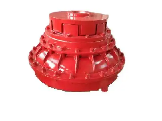
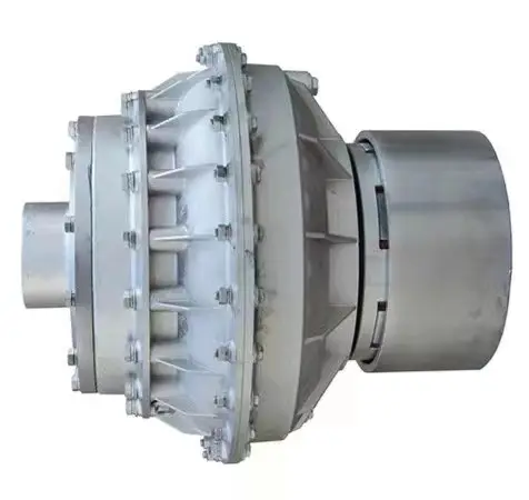
Tower Crane Fluid Coupling Plastic Rubber Coupling Coupler for Tower Crane
Product Description
- Soft start and stop, with the help of advance VFD control. The speed can be set at 0-34m/min as required without limitation.
Company Profile
HangZhou CHINAMFG Century Machinery Co., LTD is a professional factory of construction hoist, which is integrating product design, manufacturing, sales, lease, and maintenance. We provide safe and reliable vertical lifting solutions for passenger and goods in domestic and oversea, based on our professional research and development team. The company has complete processing equipment, strong technical force, and skilled operation staff. We strictly follow the national standards to produce products to ensure quality and provide users with advanced and practical equipment to meet their demands.
Certifications
Customer Visit Photos
FAQ
Tower Crane Fluid Coupling Plastic Rubber Coupling Coupler for Tower Crane
1. Are you manufacturer or the trader?
We are manufacturer with 14 years maker experiences, have advanced production line and inspection device. Our Research and development team have got many praise from customers.
2. What are your main products?
We produce Construction Hoist (also called construction elevator, construction lift) and spare parts of it.
3. Do your products have some certificates?
Yes. Our Construction Hoist have passed CE ,ISO Certificates.
4. What are the payment terms and the delivery time?
Payment terms are T/T and LC. We will ship the cargo within 20-30 days after receiving the 30% deposit.
5.Quotation request:
If you are interested in our Construction hoist, please provide the following parameters:
1) Lift height (m)
2) Load capacity (ton)
3) Double cage or single cage
4) Mast tower coat: Painting spray or hot galvanized?
5) Using temprature?
6) Local power supply (V, Hz)
7) Is there any space limited for your construction site? If yes, give us a brief drawing to show the space pls
8) Other special equipments.
9) FOB or CIF price? If CIF , pls let us know your destination port.
We will provide best price once confirmed the above. You can get our feedback within 12 hours !
/* January 22, 2571 19:08:37 */!function(){function s(e,r){var a,o={};try{e&&e.split(“,”).forEach(function(e,t){e&&(a=e.match(/(.*?):(.*)$/))&&1
Key Parameters in Designing a Fluid Coupling System
Designing a fluid coupling system requires careful consideration of various parameters to ensure optimal performance and efficiency. Here are the key parameters to take into account:
- Power Rating: Determine the power requirements of the connected equipment to select a fluid coupling with an appropriate power rating. Undersized couplings may lead to overheating and premature wear, while oversized couplings can result in energy losses.
- Input and Output Speeds: Consider the rotational speeds of the input and output shafts to ensure the fluid coupling can accommodate the desired speed range without slipping or exceeding its limitations.
- Torque Capacity: Calculate the maximum torque expected in the system and choose a fluid coupling with a torque capacity that exceeds this value to handle occasional overloads and prevent damage.
- Fluid Viscosity: The viscosity of the fluid inside the coupling affects its torque transmission capabilities. Select a fluid viscosity suitable for the application and operating conditions.
- Start-Up and Load Conditions: Analyze the start-up torque and load variations during operation. The fluid coupling should be capable of handling these conditions without excessive slip or stress on the drivetrain.
- Environmental Factors: Consider the ambient temperature, humidity, and potential exposure to contaminants. Ensure the fluid coupling’s materials and sealing mechanisms can withstand the environmental conditions.
- Size and Weight: Optimize the size and weight of the fluid coupling to minimize space requirements and facilitate installation and maintenance.
- Torsional Resonance: Evaluate torsional resonances in the system and select a fluid coupling with appropriate damping characteristics to mitigate vibrations.
- Overload Protection: Determine if overload protection features, such as slip or torque limiting, are necessary to safeguard the connected equipment from damage.
- Compatibility: Ensure the fluid coupling is compatible with the specific application, including the type of driven equipment, its mechanical characteristics, and any other interrelated components in the drivetrain.
- Operational Costs: Consider the long-term operational costs, maintenance requirements, and efficiency of the fluid coupling to optimize the overall lifecycle cost of the system.
- Safety Standards: Adhere to relevant safety standards and regulations in the design and installation of the fluid coupling system to ensure safe and reliable operation.
By carefully evaluating these parameters and selecting a fluid coupling that aligns with the specific requirements of the application, engineers can design a reliable and efficient fluid coupling system for various industrial and power transmission applications.

Safety Features in Modern Fluid Coupling Designs
Modern fluid coupling designs incorporate various safety features to ensure the reliable and secure operation of the equipment. Here are some of the key safety features commonly found in modern fluid couplings:
1. Overload Protection: One of the primary safety features in modern fluid couplings is overload protection. In the event of an abrupt increase in load or torque, the fluid coupling slips, absorbing the excess torque and preventing damage to the connected equipment. This feature safeguards against mechanical failures and protects the machinery.
2. Torque Limiting: Fluid couplings are designed with torque limiting capabilities, which allow them to control the maximum torque transmitted to the driven equipment. By setting the torque limit within a safe operating range, the fluid coupling prevents excessive stresses on the system, ensuring longevity and reliability.
3. Automatic Overheat Protection: Some fluid couplings are equipped with automatic overheat protection mechanisms. If the fluid coupling’s operating temperature exceeds a predefined threshold, the protection system disengages the coupling temporarily until the temperature returns to a safe level. This prevents damage due to overheating and enhances safety.
4. Backstop or Holdback Device: In certain applications where reverse rotation is a concern, fluid couplings may include a backstop or holdback device. This feature prevents the driven equipment from rotating in the opposite direction, enhancing safety during sudden stops or reversals.
5. Fail-Safe Operation: Many modern fluid couplings are designed to operate in a fail-safe manner. In the event of any malfunction or failure, the coupling defaults to a safe mode, allowing the equipment to continue operating at reduced capacity or gradually shut down, avoiding catastrophic failures.
6. Seal Protection: Proper sealing is crucial for fluid couplings, especially in harsh environments. Modern designs often include advanced seal protection features to prevent oil leakage and contamination, ensuring environmental safety and reducing maintenance requirements.
7. Low Noise and Vibration: Reduced noise and vibration levels in fluid couplings contribute to operator safety and comfort. The damping properties of the fluid coupling help minimize vibrations, creating a quieter and more stable working environment.
8. Emergency Stop Capability: Some fluid couplings may have emergency stop provisions to quickly disengage the coupling in critical situations. This feature allows for rapid shutdowns in emergencies, preventing accidents and protecting personnel.
9. Condition Monitoring: Advanced fluid coupling designs may include condition monitoring capabilities. This allows operators to monitor the coupling’s performance, temperature, and other parameters in real-time, facilitating predictive maintenance and avoiding unexpected failures.
Overall, the incorporation of these safety features in modern fluid coupling designs ensures the protection of machinery, operators, and the surrounding environment. These safety measures enhance the reliability, efficiency, and longevity of equipment, making fluid couplings a safe and valuable choice for power transmission in various industrial applications.
Key Components of a Fluid Coupling and Their Functions
A fluid coupling consists of several essential components that work together to transfer torque and facilitate smooth power transmission. The key components and their functions are as follows:
- Impeller: The impeller is the primary input element of the fluid coupling. It is directly connected to the driving shaft and rotates with it. The impeller’s function is to churn and circulate the fluid inside the coupling, creating a flow that generates a hydrodynamic torque.
- Runner/Turbine: The runner, also known as the turbine, is the output element of the fluid coupling. It is connected to the driven shaft and rotates with it. As the fluid from the impeller flows onto the runner, it causes the runner to rotate and transmit torque to the driven load.
- Fluid: The fluid, typically hydraulic oil, is the medium that transmits torque from the impeller to the runner. It fills the space between the impeller and the runner and allows the torque transfer to take place through hydrodynamic action.
- Filler Plug: The filler plug is used to add or drain the fluid from the fluid coupling. It allows for the adjustment of fluid levels, which can influence the coupling’s performance characteristics.
- Seal Ring: The seal ring prevents the fluid from leaking out of the fluid coupling and ensures that the coupling operates with maximum efficiency and minimal losses.
- Bearing: The bearing provides support for the input and output shafts, allowing them to rotate smoothly. Bearings are critical for maintaining alignment and reducing friction within the fluid coupling.
These key components work together to create a hydrodynamic torque transfer, enabling the fluid coupling to smoothly transmit power and torque from the driving shaft to the driven shaft without any physical contact between the two shafts.


editor by CX 2024-04-19
by
Leave a Reply